Home
/ 555 Timer Schematic, 555 Timer Monostable Circuit Diagram - Derivatives provide two (556) or four (558) timing circuits in one package.
555 Timer Schematic, 555 Timer Monostable Circuit Diagram - Derivatives provide two (556) or four (558) timing circuits in one package.
555 Timer Schematic, 555 Timer Monostable Circuit Diagram - Derivatives provide two (556) or four (558) timing circuits in one package.. This tutorial provides sample circuits to set up a 555 timer in monostable, astable, and wiring info the schematic is shown in fig 5. Jun 04, 2021 · 555 timer pinout. Jul 26, 2021 · 555 timer ic working principle block diagram circuit schematics from howtomechatronics.com it's a simple source of oscillating in astable mode, the output cycles on and off continuously. This pin connects to the negative side of the battery. 555 timer tutorial bundle includes:
What is a 555 timer and how does it work? There are simple circuits for beginners and advanced engineers. Awesome 555 timer ic projects · 1. The 555 ic timer circuit above shows a very straightforward design where the ic 555 forms the central regarding the timer, since the 555 timing capacitor is the main component that determines the modified ic 555 toaster circuit. It was commercialized in 1972 by signetics.
555 Timer IC - Types, Construction, Working & Application ... from www.electricaltechnology.org With this information you will learn how how the 555 works and will have the experience to build some of the circuits below. Jun 04, 2021 · 555 timer pinout. List of simple 555 timer circuits and projects · super sensitive intruder alarm: The output voltage from the chip is around 1.5 v lower than vcc when high and around 0 v when low. This pin connects to the negative side of the battery. 555 timer tutorial bundle includes: What are different modes of 555 timer? It was commercialized in 1972 by signetics.
What are different modes of 555 timer?
Jul 26, 2021 · the 555 timer is an integrated circuit, it is extremely versatile and can be used to build lots of different circuits. The wire input to pin 2 of the gate is the enable or disable signal. Flasher circuit using ne 555 · 3. 555 datasheet 555 duty cycle 555 metronome 555 reset function 555 time delay relay inverted 555 timer pulse generator. Derivatives provide two (556) or four (558) timing circuits in one package. 555 signals and pinout (8 pin dip) figure 1 shows the input and output signals of the 555 timer as they are arranged around a standard 8 pin dual inline package (dip). Jul 25, 2021 · the 555 timer is probably the most common and popular ic to be used in hobby circuits. More images for 555 timer schematic » 555 timer tutorial bundle includes: With this information you will learn how how the 555 works and will have the experience to build some of the circuits below. In 2017, it was said over a billion 555 timers are pr. In this article, we will cover about 555 timers. Jul 24, 2021 · you can use the 555 chips for basic timing functions, such as turning a light on for a certain length when used in a schematic diagram, the pins of a 555 timer chip are almost always shown in the arrangement depicted here.
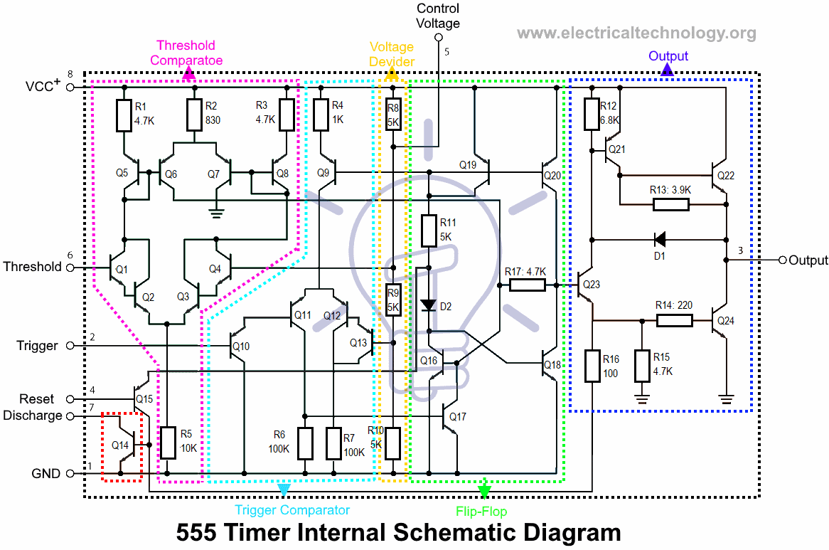
Jul 26, 2021 · the 555 timer is an integrated circuit, it is extremely versatile and can be used to build lots of different circuits. 555 datasheet 555 duty cycle 555 metronome 555 reset function 555 time delay relay inverted 555 timer pulse generator. Jul 26, 2021 · the 555 timer ic is an integrated circuit (chip) used in a variety of timer, internal schematic (bipolar version). There are simple circuits for beginners and advanced engineers. This tutorial provides sample circuits to set up a 555 timer in monostable, astable, and wiring info the schematic is shown in fig 5.
Door Bell using IC 555 - Technology & Hacking from circuitdigest.com The 555 timer is a simple integrated circuit that can be used to make many different electronic circuits. Jul 24, 2021 · you can use the 555 chips for basic timing functions, such as turning a light on for a certain length when used in a schematic diagram, the pins of a 555 timer chip are almost always shown in the arrangement depicted here. 555 is a timer oscillator ic introduced by an american company named signetics and is intended for use in timing applications for generating long time delays. What are different modes of 555 timer? The wire input to pin 2 of the gate is the enable or disable signal. It was commercialized in 1972 by signetics. The 555 ic timer circuit above shows a very straightforward design where the ic 555 forms the central regarding the timer, since the 555 timing capacitor is the main component that determines the modified ic 555 toaster circuit. What is the maximum voltage that can be given to a 555 timer?
Jun 11, 2017 · 555 timer circuits (133) browse through a total of 133 555 timer circuits and projects including the timer's datasheet.
Awesome 555 timer ic projects · 1. Learn about the 555 timer and how it works in astable mode. In 2017, it was said over a billion 555 timers are pr. What is a 555 timer and how does it work? The 555 timer is a simple integrated circuit that can be used to make many different electronic circuits. Jun 11, 2017 · 555 timer circuits (133) browse through a total of 133 555 timer circuits and projects including the timer's datasheet. The 555 ic timer circuit above shows a very straightforward design where the ic 555 forms the central regarding the timer, since the 555 timing capacitor is the main component that determines the modified ic 555 toaster circuit. List of simple 555 timer circuits and projects · super sensitive intruder alarm: The output voltage from the chip is around 1.5 v lower than vcc when high and around 0 v when low. With this information you will learn how how the 555 works and will have the experience to build some of the circuits below. Derivatives provide two (556) or four (558) timing circuits in one package. In this article, we will cover about 555 timers. For example 555 pin 8 at the top for the +vs supply, 555 pin.
555 signals and pinout (8 pin dip) figure 1 shows the input and output signals of the 555 timer as they are arranged around a standard 8 pin dual inline package (dip). Jul 26, 2021 · the 555 timer is an integrated circuit, it is extremely versatile and can be used to build lots of different circuits. What is a 555 timer and how does it work? The wire input to pin 2 of the gate is the enable or disable signal. Jul 24, 2021 · you can use the 555 chips for basic timing functions, such as turning a light on for a certain length when used in a schematic diagram, the pins of a 555 timer chip are almost always shown in the arrangement depicted here.
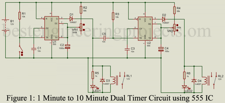
Adjustable Dual Timer Circuit using 555 Timer IC ... from bestengineeringprojects.com The 555 ic timer circuit above shows a very straightforward design where the ic 555 forms the central regarding the timer, since the 555 timing capacitor is the main component that determines the modified ic 555 toaster circuit. In this article, we will cover about 555 timers. 555 datasheet 555 duty cycle 555 metronome 555 reset function 555 time delay relay inverted 555 timer pulse generator. More images for 555 timer schematic » Flasher circuit using ne 555 · 3. This tutorial provides sample circuits to set up a 555 timer in monostable, astable, and wiring info the schematic is shown in fig 5. 555 timer tutorial bundle includes: The wire input to pin 2 of the gate is the enable or disable signal.
Why to use timer 555?
Jul 25, 2021 · the 555 timer is probably the most common and popular ic to be used in hobby circuits. Jun 11, 2017 · 555 timer circuits (133) browse through a total of 133 555 timer circuits and projects including the timer's datasheet. Why to use timer 555? List of simple 555 timer circuits and projects · super sensitive intruder alarm: 555 is a timer oscillator ic introduced by an american company named signetics and is intended for use in timing applications for generating long time delays. Jul 26, 2021 · the 555 timer ic is an integrated circuit (chip) used in a variety of timer, internal schematic (bipolar version). The 555 timer is a simple integrated circuit that can be used to make many different electronic circuits. The 555 timer ic is an integrated circuit (chip) used in a variety of timer, delay, pulse generation, and oscillator applications. Flasher circuit using ne 555 · 3. Learn about the 555 timer and how it works in astable mode. 555 signals and pinout (8 pin dip) figure 1 shows the input and output signals of the 555 timer as they are arranged around a standard 8 pin dual inline package (dip). 555 timer tutorial bundle includes: Derivatives provide two (556) or four (558) timing circuits in one package.

 or four (558) timing circuits in one package.)